TG-DMX-V003
TG-DMX-V003

Power input DC5V~24V ,Max load current 5A/CH
Max power: 360W ,Build in mode Color wash
Automatically adapts to DC5-24V.
The change patterns of various built-in, adjust the light delicate no flicker.
Accept the DMX512 signal input and transfer to the next group of decoders.
Memory function.
Working with power amplifier to expand power output unlimitedly
| Input Voltage | DC5V-DC24V |
| Output current | 5Ax3(RGB) |
| MAX power | 360W |
| Standarad mode without DMX512 signal | Color wash |
| Protocol | DMX512/1990 |
| Interface | Green terminal |
| Work temperature | -20~55℃ |
| Waterproof | IP20 |
| Dimensions | L87*W84*H25 |
| Weight | 107g |
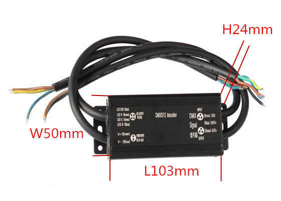
2.External dimension(mm)
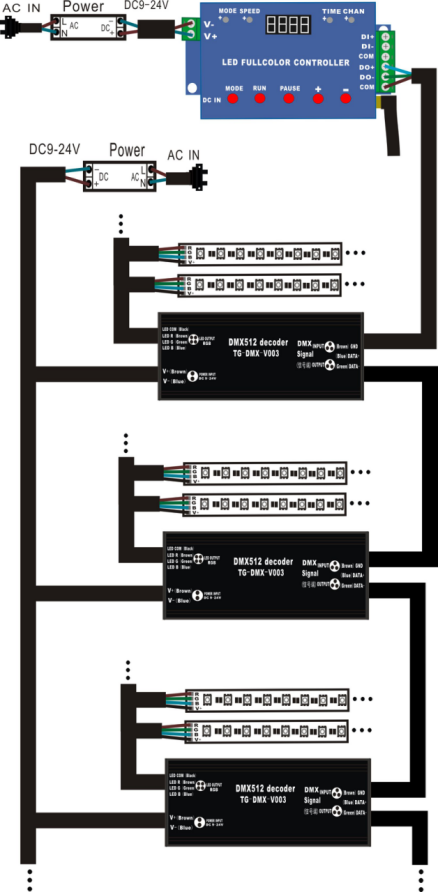
III.Controller instruction for use
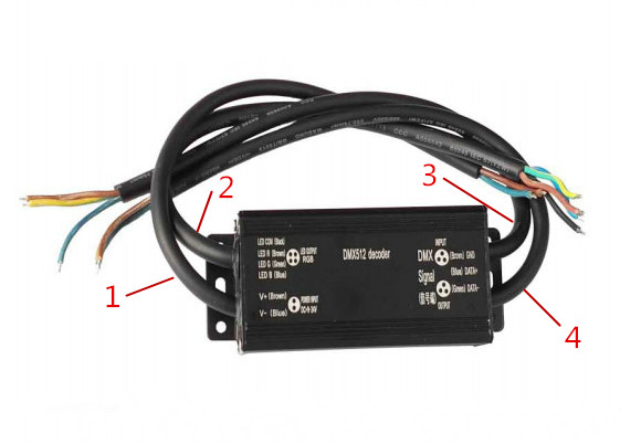
1. Input interface:the decoder power supply input.
V+(Brown): Input, the positive power supply,Line color is brown.
V-(Blue): Input, the negative power supply,Line color is blue.
2.Output interface:the decoder load output port.
LED COM(Black): Output, the positive LED lamp supply, Common terminal,Line color is black.
LED R(Brown): Output, Red color,Line color is brown.
LED G(Green): Output, Green color,Line color is green.
LED B(Blue): Output, Blue color,Line color is blue.
3.Signal intput interface:DMX512 signal intput interface.
INPUT GND(Brown):DMX512 signal intput,Line color is brown。
INPUT DATA+(Blue):DMX512 signal intput,Line color is blue.
INPUT DATA-(Green):DMX512 signal intput,Line color is green.
4.Signal output interface:DMX512 signal output interface,To next decoder.
OUTPUT GND(Brown):DMX512 signal output, To next decoder,Line color is brown.
OUTPUT DATA+(Blue):DMX512 signal output, To next decoder,Line color is blue.
OUTPUT DATA-(Green):DMX512 signal output, To next decoder,Line color is green.
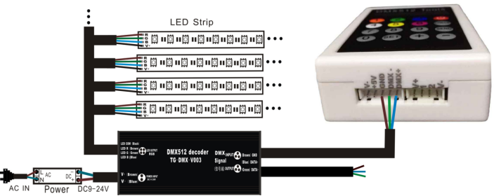
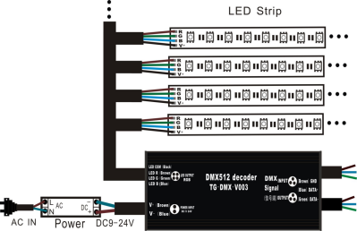
IV. Install figure
DMX512 decoder to LAMP
V. Write address code mode
DMX512 Decoder to DMX512 Tools